How To Use SimpleDraw
Video Tutorial
If you are still having difficulties after watching the video, and reading through the documentation below, try joining our Discord Server and asking for help there.
How to Use SimpleDraw
Quick links:
- Basics
- Drawing Lines
- Zoom and Navigation
- Alignment and Precision
- Measurements
- Working with Text
- Undo & Redo
- Line Properties
- Rectangles
- Images and Shapes
- Exporting Drawings
- Cloud Storage
- Save & Load (Free Users)
- Floor Plan Mode
- Additional Notes
SimpleDraw Basics
Supported Devices
At this time, SimpleDraw is designed for desktop / laptop computers with a keyboard and mouse.
Support for tablets with touchscreen controls is something I hope to deliver in the near future.
SimpleDraw is not intended to be used on mobile phones. It would be very difficult to offer a high-quality drawing experience on such a small screen.
User Interface Basics
The SimpleDraw UI has 3 key elements:
- The Toolbar, along the top
- The main drawing Workspace, which takes up the majority of the screen
- The Properties Panel to the right. This contains dynamic content depending on what tools are active, and which elements are selected.
The UI is primarily mouse-driven, but with keyboard shortcuts for some common operations (Ctrl+Z for undo, Ctrl+C, Ctrl+V for Copy/Paste, Escape, Delete, Shift-click for multiple selections etc.). See the final section of this document for a complete list.
The Toolbar contains 6 areas, from left to right:
-
Click tools. These are tools that are activated by clicking on the drawing. E.g. the Line Tool

-
Drag tools. These are tools that are activated by holding down the mouse button, and dragging the mouse with the mouse button down. E.g. the Move Tool

- An important point to note is that a “Click Tool” and a “Drag Tool” can be active at the same time. SimpleDraw will apply the appropriate tool, depending on whether the mouse is clicked, or dragged. See also notes on “Tool Selection” below.
-
Hints panel. This contains context-dependent hints and instructions, and controls to scroll through the available hints.

-
Actions. These buttons trigger actions like Undo, Redo, Copy, Paste and Delete.

-
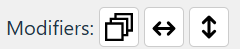
Modifiers. These indicate when a key is held down that modifies the behaviour of a tool, e.g. Shift, or the Vertical / Horizontal constraints.
-
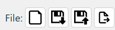
File operations. New Drawing, Save, Load, Export.
Each of these tools is explained in the following sections.
Drawing Lines
To draw a line
- Select the Line Tool:

- Start the line by clicking where you want the line to start
- Click again at the point you want the line to end.
- After drawing a line, the line tools is de-selected. To draw a second line, select the line tool again (or use the Multiline Tool
To modify a line (option 1)
-
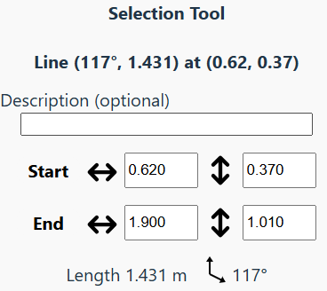
Use the Select Tool:

-
Click on the line to select the line
-
In the right panel, adjust the co-ordinates of the start and end points as required
-
(note: you can also directly modify the length or angle of the line using the right panel - see Line Properties)
To modify a line (option 2)
-
Use the Move Tool:

-
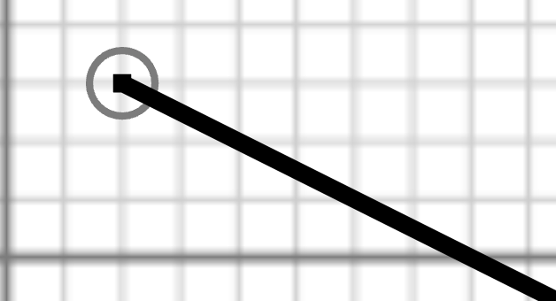
Hover over either the start or end point: a circle should appear around the point.
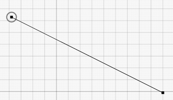
-
Hold the mouse button down, and drag the point to the desired position.
-
SimpleDraw will attempt to intelligently snap to positions for the far end of the line, based on the drawing grid, line length, and other points and lines in the drawing - see Alignment and Precision below.
-
You can use the mouse wheel to zoom in for finer control:
To draw multiple connecting lines
- Hold down “Shift” to draw multiple connecting lines
- Or use the Multiline Tool

- Lines will stop when you finish at an existing point or line
- Press the Escape key to stop at any time…
- … or just deselect the Multiline Tool to finish.
To draw horizontal or vertical lines
- Hold down H or X to constrain a line to be horizontal
- Hold down V or Y to constrain a line to be vertical
- Or: Hold down C to constrain a line to be either horizontal or vertical.
Zoom and Navigation
SimpleDraw aims to offer high levels of precision and accuracy, and zoom capabilities are a key part of this.
There are multiple different zoom mechanisms offered by SimpleDraw, to allow for user convenience
Mouse Wheel Zoom
The mouse wheel can be used to zoom in and out of the drawing, to any level, at any time.
When zooming using the mouse wheel, the zoom will be centered on the mouse pointer, so make sure the pointer is over the area that you wish to zoom in to.
Zoom Tool
The Zoom Tool  is located in the Click Tools Toolbar. When the Zoom Tool is selected, you can zoom in using left click, and zoom out using right click. Again, the zoom will be centered on the mouse pointer.
Zoom Slider
The Zoom Slider is located at the top of the Properties panel.
This can be used to zoom in/out at any time. The zoom will be centered on the middle of the drawing.
Quick Zoom
At any time, you can press and hold Z for a quick 5x zoom, centered on the current mouse pointer position.
When the Z key is released, the drawing will return to the original zoom.
Scroll Bars
When the zoom level means that the whole drawing is not visible in the workspace, scroll bars will appear on the right and bottom of the workspace.
Use these scroll bars to navigate around the drawing without zooming out.
Alignment and Precision
When drawing lines, or moving the points that form a line SimpleDraw uses a number of different heuristics as a basis for suggesting specific positions for points.
Various green indicators are used to show why a particular position is being suggested.
You will see the following indicators:
| Indicator | Visual | Meaning | |
|---|---|---|---|
| Grid | 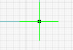 | The point is aligned with the reference grid for the drawing | |
| X/Y Offset | 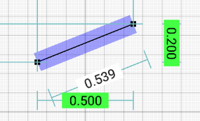 | The point is at a particular offset along the X and Y axes from another point. This could be the other end of a line being drawn, or some other point in the drawing. | |
| Length | 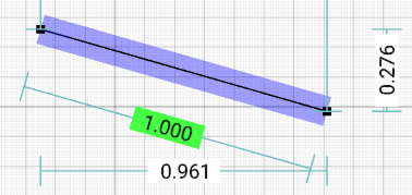 | The point forms a line of a particular length. | |
| Parallel | 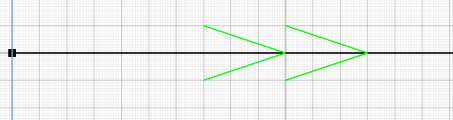 | This appears on an existing line, when a new line being drawn runs parallel to it. When this appears, a point is being suggested that results in the two lines being exactly parallel. | |
| Distance from Line | 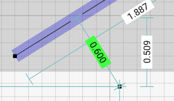 | This appears when a point is a particular distance from a line. To avoid clutter, this indicator only activates when a line is selected. |
If you care about the position of a new point or line relative to some other existing point or line, you can select that line before selecting the line tool. This will result in the alignment system focusing on alignments relative to that point or line.
Precision
The alignment system is directly affected by the Precision setting on the drawing. This can be seen in the top-right corner, just below the zoom setting.
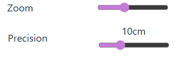
The precision setting determines how precisely the alignment system operates. For example, if precision is set to 10cm, then alignments will snap to positions at 10cm intervals: 0.1m, 0.2m, 0.3m etc. Whereas if precision is set to 1cm, then alignments will snap to positions at 1cm intervals.
When you zoom into a drawing, precision automatically increases to match the zoom level. However you can also directly control the precision level independently of zoom by adjusting the precision slider.
Measurements
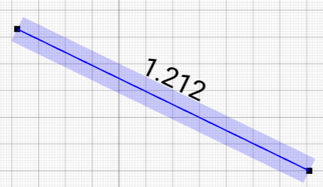
When positioning points and lines, SimpleDraw dynamically shows a range of potentially useful measurements, to assist with accurate placement of points and lines.
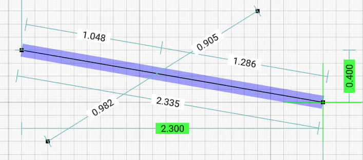
Measurements that are shown include:
- The overall lengths of lines selected, or being drawn
- The lengths of segments of lines between points of intersection with other lines
- Offsets in the horizontal and vertical directions
- Distances from the edges of the drawing, again in both horizontal and vertical directions.
As well as these dynamic measurement displays, individual lines can be explicitly configured:
- To always show certain measurements
- Or to never show measurements
Where lines have a non-zero width, measurements along the line can be different depending on which side of the line is being measured. Again, lines can be configured to show measurements along their inside, outside or center. See Line Properties for full details.
In some circumstances, the number of different measurements displayed could potentially be overwhelming. You can reduce the level of measurements being shown in a few ways:
- Ensure lines or points aren’t selected. Selecting lines and points results in additional measurements being displayed, that wouldn’t be otherwise.
- Explicitly configure some lines to not display measurements.
- A “Minimum Display Value” can be set for measurements, either for the drawing as a whole, or for individual lines. Measurements below this length won’t be shown, helping to reduce clutter associated with very small measurements.
- Press the space bar, or select the “Hide Measurements” modifier to temporarily hide all dynamic measurements (“contextual measurements”). Explicitly configured measurements will still be visible.
Working with Text
To add text
-
Select the Text Tool:

-
Position the text where you want it on the drawing
-
Use the right panel to adjust the text content, position and font size as required. You can adjust the text and font size either before or after you place the text.
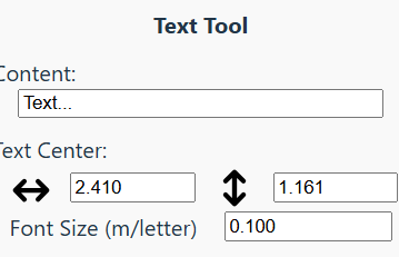
-
When you have finished placing text, deselect the Text Tool.
Modifying or moving text
- Use the Select Tool:
- Click on the text to select it
- Use the right panel to adjust the text content, position and font size as required.
- You can also reposition text by dragging it using the Move Tool:
- You can also reposition text by dragging it using the Move Tool:
Undo and Redo
The Undo  and Redo
  buttons can be used at any time to undo (or redo) recent operations.
You can also use Ctrl+Z as a shortcut for Undo, and Ctrl+Y or Shift+Ctrl+Z as a shortcut for Redo.
SimpleDraw tracks the last 100 changes made to a drawing, so can undo up to 100 operations.
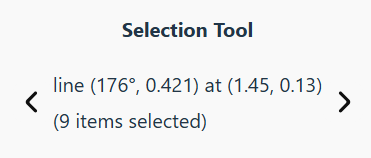
Selecting Multiple Elements
You can select one or more drawing elements. When a group of elements is selected, you can:
-
modify the properties of any element in the group using the right panel
-
move group of elements as a whole using the Move Tool:
-
duplicate the entire group of elements, using the Copy
 and Paste
  Tools (or Ctrl+C & Ctrl+V keyboard shortcuts)
You can also select all elements in the drawing using the Ctrl+A keyboard shortcut
To select multiple elements
Using the Select Box Tool:
-
Choose the Select Box Tool
-
Use the mouse to drag a selection area
-
All elements within that selection area will be selected.
Or, using the Select Tool:
-
Choose the Select Tool:
-
Hold down the Shift key
-
Click on each of the elements to be selected.
With multiple elements selected…
- In the right panel, you can use the left and right arrows to navigate between selected elements:
- the entire selection can be moved using the Move Tool:
- the entire selection can be duplicated using the Copy and Paste Tools (or Ctrl+C & Ctrl+V keyboard shortcuts)
Line Properties
In addition to their start and end points, lines have some other properties that can be useful to modify.
These properties can be modified using the right panel, after selecting a line using the Select Tool:
Fixed Direction
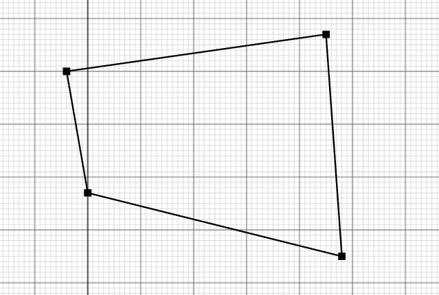
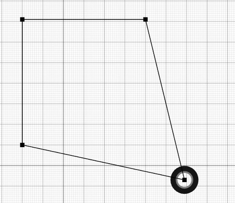
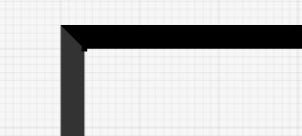
When the “fixed direction” property is set, the direction of the line is fixed. This means that if one end of a line is moved, the other end of the line moves with it, to preserve the direction of the line (although not it’s length)
For example, this means that moving the corner of a rectangle will result in a change to the dimensions of the rectangle, with right angles preserved.
This image shows what happens if you move the corner of a rectangle, and “fixed direction” was not set on both sides of the rectangle.
By default, lines do not have “fixed direction”, unless they were created by the Rectangle Tool  . But you can set fixed direction on any line. The only constraint is that no more than two lines meeting at a point can have “fixed direction”.
Line Width
By default lines have no width. They will be rendered a single pixel wide, whatever your zoom level.
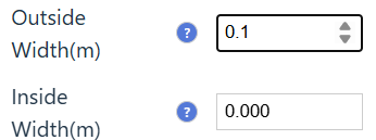
However you can also configure lines to have a specific width. This width can be on the “outside” of the line, on the “inside” of the line, or on both sides (note that all lines have a direction from their “start point” to their “end point”, and the “outside” of the line is the left hand side of the line, as you move along the line from “start” to “end”).
When a line has width, and it meets one other line at a point, the line shapes are adjusted to make a neat corner. There are some limits on this function, to avoid extremely long, sharp corners, and complex cases where 3 or more lines meet at a point, but they should result in neat corners in most cases.
Measurements
There are quite a few settings on a line to control measurements, particularly for lines that have non-zero width.
For lines with zero width, the following settings are available:
Show Measurements
This controls what measurements will be shown.
- Never: Never display measurements for this line.
- Contextual: Display measurements relevant to the current selected line.
- Length: Always display total length of the line.
- Intervals: Always display measurements of items along the line. These are only shown when the line crosses another line, or contains an embedded item.
- Length + Intervals: (not always available) Always display both the total length of the line, and measurements of items along the line.
Show where?
For explicitly configured (i.e. non-contextual) measurements, there is the option to display them either along the line, or at the edges of the drawing (on the right hand side, and at the bottom):
- Adjacent: Show measurements beside the line.
- Edges: Show vertical and horizontal measurements at the edges of the drawing. When this is selected, contextual measurements will be shown adjacent to the line when relevant.
Min Display Value
This can be configured so that measurement values are not shown when they are below a certain threshold, reducing clutter.
For lines with non-zero width, there are separate groups of settings for measurements on the inside of the line, the outside of the line and (where appropriate) the center of the line. The settings are just the same as described above, but allow independent control of measurements on either side of the line.
Rectangles
The Rectangle Tool is a handy shortcut for drawing 4 lines to form a rectangle.
(Note that you can also add a rectangle directly to your drawing using the Rectangle Shape  - see below - the Rectangle Shape is simpler, and allows for curved corners, but you can’t adjust individual points).
To draw a rectangle
-
Select the Rectangle Tool
-
Click where you want the top left corner of the rectangle
-
Move the mouse to the bottom right corner of the rectangle, and click again.
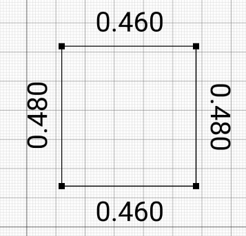
-
The dimensions of the rectangle are shown while it is being drawn. If you want to continue to show dimensions after the rectangle is drawn, you can adjust the line properties.
To modify a rectangle
Once a rectangle is created, it becomes a collection of lines, which can be independently modified or deleted.
- To move the rectangle as a whole, you will need to select all 4 points, or 4 sides, using the Select Box, or Shift+Select Tool. Once you have selected the 4 points or 4 sides, you can move the rectangle using the Move Tool:
- To adjust the size of the rectangle, just select any corner point, and move it using the Move Tool, or the properties of the point.
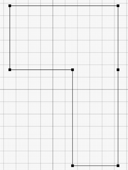
- You can also modify the sides of the rectangle individually. For example, you can remove one side of a rectangle to join it with another, like this:
Images and Shapes
Images
Users with paid Cloud Storage accounts can add images to their drawings.
This can be particularly useful for:
- Adding custom items to a drawing or floor plan
- Tracing over an existing drawing or floor plan that comes from another source.
Adding an Image to a Drawing
Adding an image to a drawing is similar to adding shapes and text. Select the Image Tool  and then click to place the image.
Initially, a placeholder icon will be shown. In the Properties panel, you can then change the image displayed. You can either display an image that you already uploaded to your Image Storage, or upload a new image.
Images can be uploaded in PNG, JPEG or WEBP formats. If you have a PDF or SVG file that you wish to include in your drawing, you’ll need to convert it to one of these formats first.
Various free tools are available for this, for example you can use these tools to convert to PNG format.
Please note that by uploading images, you grant certain rights to us to distribute these images. You should not upload images that you do not have the right to distribute. For full details, see our Terms and Conditions.
Foreground and Background Images
When images are in the foreground of the drawing, they behave just like other items in the drawing (text, shapes, floor plan items etc.). You can move them around using the move tool, and adjust their size and rotation using the Properties panel.
Images are layered so that smaller images appear in front of larger images. We don’t yet have a system for controlling these layers.
Images can also be set to the drawing background (using a “Set to Background” button in the Properties panel). When an image is in the background, you can’t interact with it, meaning that you can trace over it without any risk of moving the image itself.
Background Images are listed in the Drawing Properties panel  If you want to modify the size or position of a background image, you can bring it to the foreground, modify it as required, and then set it to the Background again.
Image Storage
When you upload an image, it is uploaded to your Image Storage.
You can access your Image Storage at any time, by opening your Cloud Storage (  ), and then clicking the Images button in the top right corner ( )
This will show all images currently uploaded to your Image Storage.
Click on an image to enlarge it. To delete an image, click on it, and then press the Delete button (  )
)
Note that the Image Store is the primary location in which images are stored. When you download or share a drawing, the downloaded or shared drawing includes a reference to the image, but not the image content itself. So if you delete the image from your Image Storage, then it will no longer be visible in any drawings that included that image. Be careful which images you delete!
Cloning Images
When a drawing is shared with you, or you view a public drawing it may include images.
When Cloud Storage subscribers take a copy of that drawing, they have the option to clone the images. If they clone the images, they will have copies of all the images in their own image storage. Otherwise, their copy of the drawing will continue to reference the images in the original author’s image storage, meaning that they will only be visible as long as the original author keeps those images in their image storage.
For images that are not cloned, they can always clone that image into their own image storage at a later point, using the “Clone this Image into Your Cloud Storage” button, which can be found in the image Properties panel.
For users without a Cloud Storage subscription, images will always reference the copies in the original author’s image storage, and will only remain visible as long as the original author keeps those images in their image storage.
Shapes
In addition to being able to draw lines, you can also add basic shapes to your drawing.
- Rectangles, with adjustable line width and corner radius
- Circles and Ellipses, with adjustable line width, and configurable start/end positions, meaning you can draw shapes like semi-circles and elliptic arcs.
To add a shape, select the relevant tool, and then position it where you want in your drawing. Properties such as the line width, corner radius etc. can be set in the Properties panel on the right. You can also rotate the shape using the Properties panel.
When you are in Floor Plan mode, these shapes are available under the Shapes menu:  Use them in your floor plans to represent anything for which we don’t have a built in item: rugs, skylights, oval tables etc.
Exporting or Sharing your Drawing
To share a drawing outside of SimpleDraw, you will need to Export it.
SimpleDraw supports exports in PNG image format.
To export an image
- Press the Export Button:

- Choose whether to include the background grid & point markers, and choose an image resolution
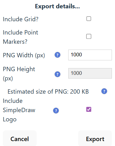
- Press the “Export” button.
The image will be downloaded to your “Downloads” folder.
Sharing a Drawing
You can also share your drawings with other users within SimpleDraw.
Cloud Storage subscribers can share drawings either privately (just accessible to those who have the link), or publicly in the Gallery where they will be accessible to anyone.
Other users can share up to 5 public drawings in the Gallery To share drawings privately, or to share more than 5 drawings, you will need to sign up for a Cloud Storage Plan.
To share a drawing, press the Share button : 
This will create a pop-up window displaying the current sharing details for the picture, and the options to
- make the drawing Public
- share via private link (Cloud Storage subscribers only)
- make the drawing Private (if it’s currently public or shared)
In this pop-up, users can also edit their Display Name that is shown alongside drawings, crediting them as the creator of the drawing. This name will be the same for all of their drawings.
When another user accesses your drawing via the link, they will see the drawing in read-only view, so they can’t modify your original drawing. However they can make a copy of their own, and make edits to that - and even share that back with you.
For full terms and conditions around sharing drawings, see our Terms and Conditions.
To stop sharing a drawing, press the Cloud Storage button , where you can modify the sharing status of any drawings that you have shared, or delete the drawing altogether.
Cloud Storage
For users with Cloud Storage storage accounts, drawings are automatically saved to Cloud Storage.
Pressing the Save Button  creates a versioned checkpoint of the drawing at this point in time.
Checkpoints are also made at the point you load a drawing from your Cloud Storage. You can have up to 10 saved versions of a drawing. You can view the previous versions of a drawing by pressing the History Button:  .
.
For Cloud Storage users, the Load Button  brings up a list of all the drawings available in your Cloud Storage.
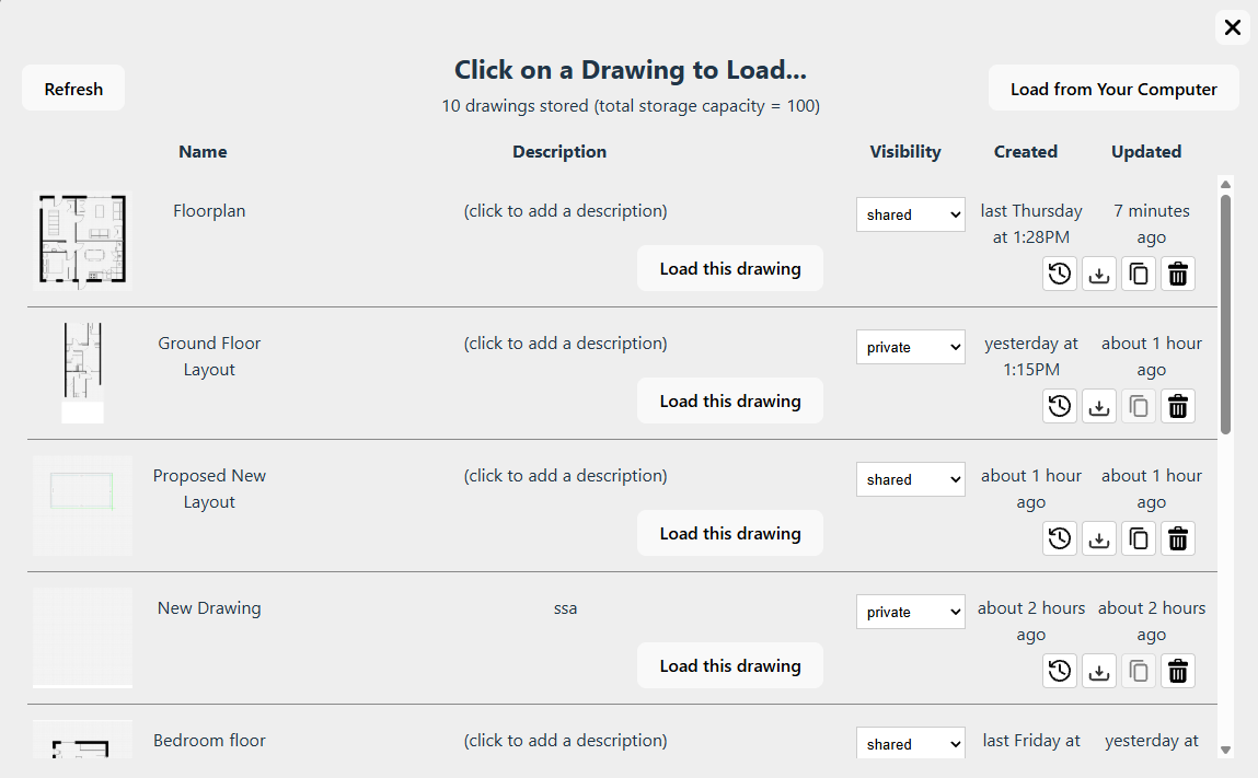
You can select a drawing to load.
From this vew, you can also:
- Change the name, or description of the drawing
- Change the visibility of the drawing to private, shared or public
- View the history of a drawing
- Download a drawing
- Copy a link to a drawing (if it’s shared or public)
- Delete a drawing.
If you want to load a drawing from your computer, you can do so using the “Load from Your Computer” button in the top right corner. When you load a drawing that’s not already in your cloud storage, it will automatically be saved in your cloud storage.
Finally, the Cloud Storage button provides another way to view all your cloud drawings. This is available not only for Cloud Storage subscribers, but also provides a way for users who have Public Shared drawings to manage those.
Version History
The version history of a drawing can be accessed via the History Button: , either from the main toolbar, or from within a Cloud Storage pop-up.
This opens a further pop-up window showing all available versions of the drawing.
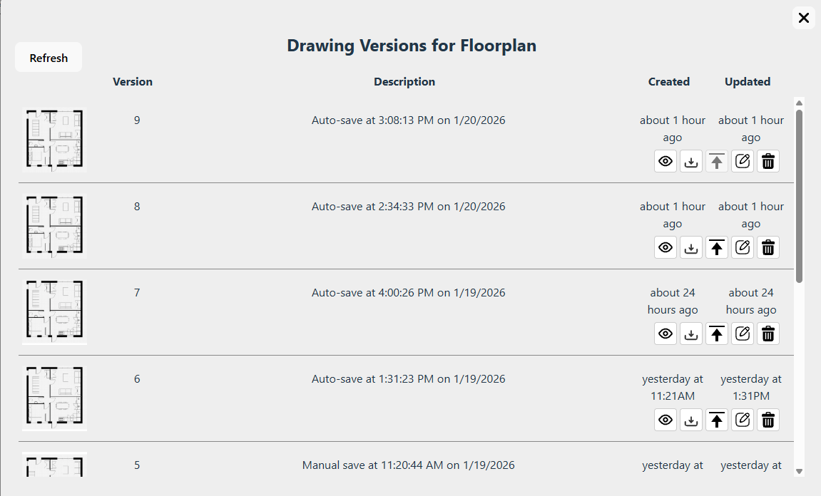
From here, you can perform various operations on older versions of the drawing:
- View a read-only version
- Download this version
- Promote an older version - in which case it becomes the latest version
- Open the version as a new drawing for editing (this will create a new drawing, with a new version history)
- Delete this individual version.
We can store up to 10 historical versions of a drawing. When you load or save a drawing that already has 10 versions, a pop-up appears to warn you about the situation. From here you can:
- Select one or more old versions to discard
- Save the current version as a new drawing (allowing a further 10 versions to be saved)
- or Continue without saving.
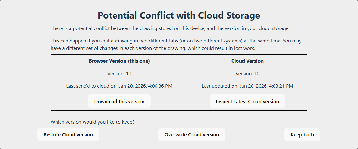
Conflicts
With cloud storage, it is possible to open the same drawing for editing in two different tabs. This could be two different tabs on the same device, or on different devices.
This is not recommended, but it can happen by accident.
SimpleDraw does not support collaborative editing across multiple tabs, so edits made in one tab risk being overwritten by changes in another. To avoid this happening, in the event of a conflict you will see a warning pop-up. You can choose which of the two versions to keep - or even keep both as separate drawings, if you prefer.
Save and Load (Free Users)
Users who don’t wish to pay for a Cloud Storage account can also save drawings, and load them again later. Files will be saved to your Downloads folder.
We recommend that you move these files to a safe and better organized location for long-term storage. Alternatively, consider using out Cloud Storage service which is a much more convenient way of storing your drawings.
To save a drawing
To save a drawing to your computer for future use in SimpleDraw:
- Press the Save Button
- This will save the drawing data to a file in your downloads folder.
- Note that this file is in a propretary format used by SimpleDraw. You won’t be able to view the drawing in a file, other than by re-loading it within SImpleDraw.
- Each time you save a file, SimpleDraw will create a new file in your Downloads folder. Filenames contain a timestamp, so they should never clash with each other. You should move these files to to a safe location for long-term storage.
Note that Saving a drawing is different from Exporting a drawing (see above).
- Exporting creates a PNG file, which is an image, and doesn’t contain all the structural information about the drawing.
- Saving creates a JSON file that contains all the structural information about the drawing, but isn’t viewable as an image without loading it back into SImpleDraw.
To load a saved drawing
If you want to work further on a saved drawing (or if you want to export it to a PNG file), you can load a saved drawing as follows:
- Press the Load Button
- This will open a file-picker window. Navigate to the file that you wish to load, and select “Open”. This should be a JSON file that you saved from SimpleDraw.
- The file should open in SimpleDraw.
- Note that next time you save the file, it will create a new timestamped save file in your Downloads folder - the file that you loaded will not be modified.
Floor Plan Mode
Floor Plan mode provides a few extensions to the basic functionality of SimpleDraw, specifically intended to support drawing floor plans.
Activating Floor Plan Mode
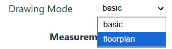
To activate floor plan mode.
- Show drawing properties, by choosing the “Select” tool and clicking on a blank part of the canvas
- Under “Drawing Mode”, select “floor plan”
When you enter floor plan mode, you will see an additional toolbar to the left of the drawing.
You can also access floor plan mode directly via this URL: https://simpledraw.app/draw/#mode=floorplan
Floor Plan Tools
The following tools are available:
-
External Wall

- When this is selected, the line tool is modified to draw wider lines, representing external walls. External walls have significant width (300mm - configurable) to the outside of the line.
- You can use either the line tool, the multiline tool, or rectangle tool to draw external walls.
-
Internal Wall:

- When this is selected, the line tool is modified to lines, representing internal walls. Internal walls have 50mm of width on either side of the line, for a total width of 100mm (again configurable).
- You can use either the line tool, the multiline tool, or rectangle tool to draw external walls.
-
Door:

- The door tool can be used to add doors to (internal or external) walls.
- Select the door tool, position your mouse where you want the door, and click to place it.
- Various properties can be set on the door, including its position, width, direction of opening, and the hinge side.
-
Window:

- The window tool can be used to add doors to walls (typically external walls, though it can also be used with internal walls)
- Select the window tool, position your mouse where you want the window, and click to place it.
- Various properties can be set on the window, including its position, width, number of segments, and its offset relative to the wall.
There are also a range of additional items that can be added to floor plans:
- Staircase
- Bathroom Items
- Bedroom Items
- Living Room Items
- Kitchen Items
I expect to extend the range of items, and their configurability over time. Specific feedback or requests is always welcome - see the contact page here.
Additional Notes
Some additional notes that may be useful for non-beginners to understand aspects of SimpleDraw in more detail.
These have been deferred to the end of this document to avoid over-complicating things for people getting started with SimpleDraw.
Tool Selection
As noted in the section on SimpleDraw Basics, a “click tool” and a “drag tool” can be active at the same time. This provides convenience, and save on frequent tool swapping. However, it can also lead to some confusion.
I’ve done quite a bit of user testing in this area, and fine-tuned the tool selection logic to address the most common sources of confusion.
The principles of tool selection are as follows:
- You can always see what tools are active, by observing which tool buttons are shaded slightly darker.
- There can be at most one “click tool” and one “drag tool” active at any one time.
- Clicking on most tools toggles that tool between “active” and “inactive”. However some tools (Line, Multiline, Rectangle) toggle through 3 states: “active”, “uniquely active”, “inactive”. Making a tool “uniquely active” deactivates any other active tool.
- If all tools are inactive, the “select” tool gets activated by default - to avoid a situation where there are no active tools.
- The Multiline and Rectangle and Text are automatically deactivated after each use (resulting in the “select” tool being activated). You can override this behaviour by holding down “Shift” to use a tool multiple times.
- When no “drag” tool is active, certain “click” tools (Line, Multiline, Rectangle) can be used by dragging from start to end, as an alternative to clicking a start and end point. This won’t work when a “drag” tool such as the Move Tool or the Select Box Tool is active.
While this may seem complicated, this combination of rules seems to be a good fit for most of the common workflows with SimpleDraw, avoiding most of the common scenarios I have seen where users get confused about tool selection.
Keyboard Shortcuts
Here’s a list of all the keyboard shortcuts available:
| Shortcut | Operation |
|---|---|
| Escape | cancel the current action |
| Delete or Backspace | delete the selected drawing element |
| Shift | allow multiple consecutive uses of a tool - e.g. combine multiple select boxes, draw multiple sequential lines. |
| H or X | constrain movement or line direction to horizontal |
| V or Y | constrain movement or line direction to vertical |
| C | constrain movement or line direction to either vertical or horizontal |
| Ctrl+Z | undo |
| Ctrl+Y or Ctrl+Shift+Z | redo |
| Ctrl+A | select all |
| Ctrl+C or Ctrl+Insert | Copy |
| Ctrl+V or Shift+Insert | Paste |
| Ctrl+D | duplicate (i.e. copy+paste) |
| Ctrl+S | save drawing |
| Ctrl+O | load drawing |
| Ctrl+N | new drawing |
| Ctrl+E | export drawing (this opens the export panel, you then need to adjust settings and click “Export”) |
Note that on Mac computers, the Command key (⌘) can be used in place of the Ctrl key in these shortcuts.
I'd Love to Hear From You
Have questions about SimpleDraw, or need help getting started?
I would particularly appreciate any feedback about how I could make SimpleDraw easier to learn, or easier to use.
Join us on Discord
Click here to join our Discord server.Follow Us on Social Media